This guide illustrates how to configure a GRE tunnel between Netskope and a FortiGate firewall device. This configuration example uses a FortiGate device running FortiOS version 6.4.9. It can work for all FortiOS versions.
Creating the GRE Tunnel in Netskope
To create the GRE tunnels for FortiGate in the Netskope UI, see Creating a GRE Site.
Configuring the GRE Tunnel in FortiGate
Enter the following CLI commands to configure the GRE tunnel:
config system gre-tunnel
    edit "GRE-NETSKOPE"
        set interface "port1"
        set remote-gw 163.116.174.36
        set local-gw 192.168.1.17
    next
end
Note the following:
- For
remote-gw, enter the IP address you copied of the Netskope POP. In this example, it’s the MRS1 GRE Gateway. - For
local-gw, enter the IP address of the interface facing the internet. In this example, the FortiGate firewall is installed behind the ISP router and has a private IP address of 192.168.1.17, which is SNAT to 109.210.55.51.
Configuring the GRE Interface
There are two options to complete the remaining GRE configuration: CLI and GUI. The CLI is faster.
You must configure the GRE interface that FortiGate automatically created when you configured the GRE tunnel.
FortiGate CLI Configuration
Enter the following commands to configure the GRE interface:
config system interface
    edit "GRE-NETSKOPE"
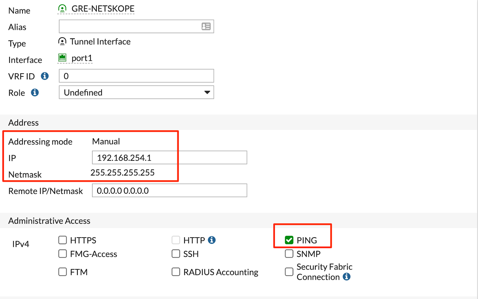
        set ip 192.168.254.1 255.255.255.255
        set allowaccess ping
        set interface "port1"
    next
end
FortiGate GUI Configuration
- Go to Network > Interfaces.
- Edit GRE-NETSKOPE.
- Configure the following GRE interface:
- Click OK.
Creating a Static Route
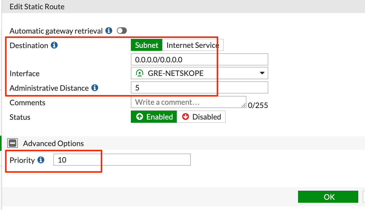
You must create a static route for the GRE interface. Note the distance and priority values.
FortiGate CLI Configuration
Enter the following commands to configure a static route:
config router static
    edit ### enter a digit number that doesn’t overlap with existing policies
        set distance 5
        set priority 10
        set device "GRE-NETSKOPE"
    next
end
FortiGate GUI Configuration
- Go to Network > Static Routes.
- Click + Create New.
- Configure the following static route:
- Click OK.
Enter the following command to verify that the two default routes are installed correctly:
get router info routing-table all
 |
Creating Policy-Based Routes
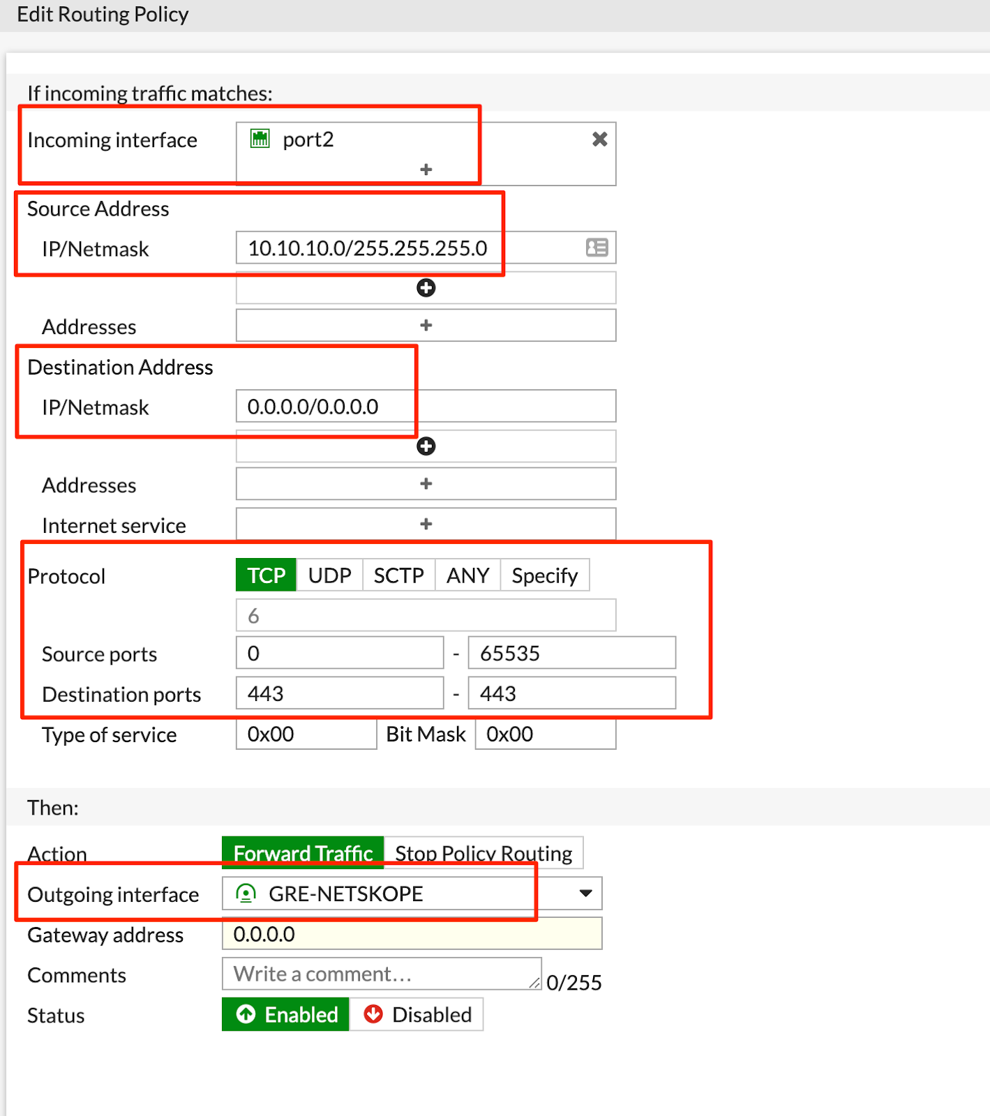
You must create policy-based routes (PBRs) to route traffic through the GRE tunnel. This example routes all HTTP and HTTPs traffic from the LAN interface (i.e., port2 10.10.10.0/24).
FortiGate CLI Configuration
Enter the following commands to create PBRs:
config router policy
    edit ### enter a digit number that doesn’t overlap with existing policies
        set input-device "port2"
        set src "10.10.10.0/255.255.255.0"
        set dst "0.0.0.0/0.0.0.0"
        set protocol 6
        set start-port 443
        set end-port 443
        set output-device "GRE-NETSKOPE"
    next
    edit ### enter a digit number that doesn’t overlap with existing policies
        set input-device "port2"
        set src "10.10.10.0/255.255.255.0"
        set dst "0.0.0.0/0.0.0.0"
        set protocol 6
        set start-port 80
        set end-port 80
        set output-device "GRE-NETSKOPE"
    next
end
FortiGate GUI Configuration
- Go to Network > Policy Routes.
- Click + Create New.

- Configure the following routing policy for HTTPS traffic:
- Configure the following routing policy for HTTP traffic:
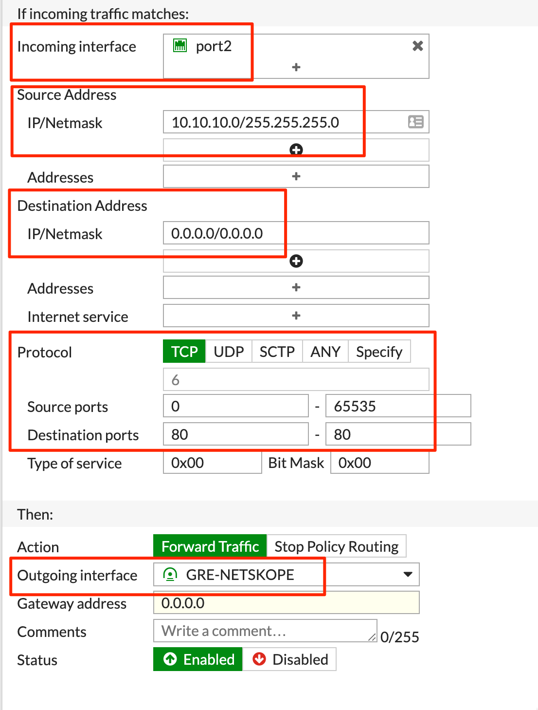
- Click OK.
Creating a Firewall Policy
You must create a firewall policy to allow traffic from the LAN interface to the GRE tunnel interface. This example uses an address object to identify the LAN subnet.
FortiGate CLI Configuration
Enter the following commands to create a firewall policy:
config firewall address
    edit "LAN"
        set associated-interface "port2"
        set subnet 10.10.10.0 255.255.255.0
    next
end
config firewall policy
    edit ### enter a digit number that doesn’t overlap with existing policies
        set name "to Netskope GRE"
        set srcintf "port2"
        set dstintf "GRE-NETSKOPE"
        set srcaddr "LAN"
        set dstaddr "all"
        set action accept
        set schedule "always"
        set service "HTTP" "HTTPS"
    next
end
FortiGate GUI Configuration
- Go to Policy & Objects > Addresses.
- Click + Create New.
- Create the following address object. Change the subnet to your LAN subnet:
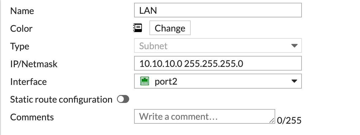
- Click OK.
- Go to Policy & Objects > Firewall Policy.
- Click + Create New.
- Create the following firewall policy:

For Service, you can select HTTP and HTTP or ALL if you have Cloud Firewall. - Click OK.
Troubleshooting
After the GRE tunnel is configured, the interface is always up. Following are some helpful tips for verifying and troubleshooting the configuration:
- Enter the following command to create a monitor server and verify that traffic is going through the tunnel:
config system link-monitor
    edit "0"
        set srcintf "GRE-NETSKOPE"
        set server "10.174.6.209"
    next
end
You can use this command to monitor the connectivity to the probe IP address of the Netskope POP.
- Enter the following command to see if the link monitor is working:
diagnose sys link-monitor status
You should see a similar output:

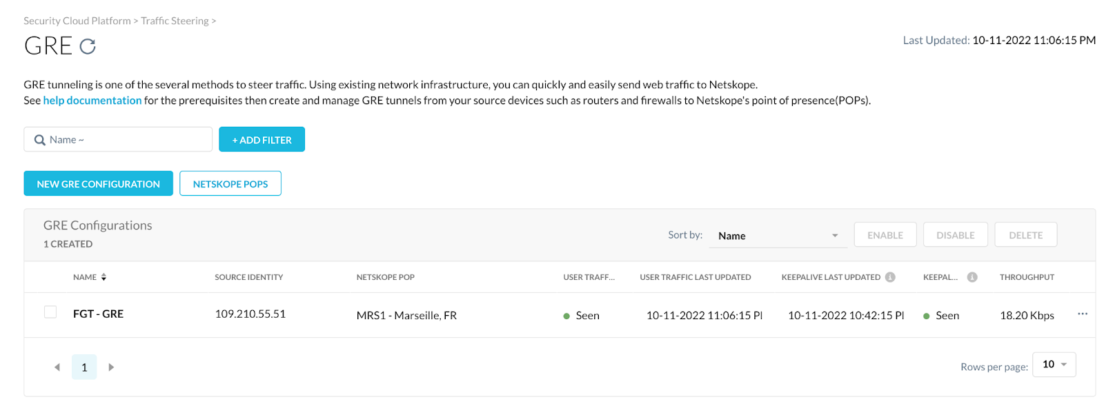
- In the Netskope UI, ensure there is a Seen status for the User Traffic and Keepalive columns: