

Netskope’s on-premises Cloud Access Security Broker (CASB) provides the ability to process and maintain data inside an enterprise’s perimeter. The N1000, N2000, and N5000 appliances are the cornerstone of this service as they provide a physical footprint.
Note
This document is dedicated to the full on-premises deployment mode; there’s a separate guide if you are managing appliances from the cloud.
When installed, your appliances should be using the latest software package.
New N2000 Appliances
The new N2000 Appliances are 1U appliances.
 |
The front of the unit has a removable bezel.
 |
When the bezel is removed, you can see a control panel with a power button and status LEDs.
 |
The following table describes the control panel.
| Label Number | Name | Description |
|---|---|---|
| 1 | Power button | The main power switch powers on or off the appliance. When switch maintains a standby power from the power supply to the appliance. |
| 2 | UID button and LED | The unit identification (UID) button powers on or off the blue light function of the Information LED and a blue LED on the rear of the chassis. The blue LEDs are used to locate the server in large racks. |
| 3 | Power LED | Indicates power is being supplied to the system power supply units. This LED is illuminated when the system is operating normally. |
| 4 | HDD | Indicates activity on the hard drive when flashing. |
| 5 | NIC LED for LAN1 | Indicates network activity on LAN1 when flashing. |
| 6 | NIC LED for LAN2 | Indicates network activity on LAN2 when flashing. |
| 7 | Information LED | Alerts operator to several states, as mentioned in the table below. |
The following table describes the various states of the Information LED.
| Information LED Status | Description |
|---|---|
| Continuously on and red | An overheating condition has occurred. This may be caused by cable congestion. |
| Blinking red (1Hz) | Fan failure, check for an inoperative fan. |
| Blinking red (0.25Hz) | Power failure, check for a non-operational power supply. |
| Solid blue | UID has been activated locally to locate the server in a rack environment. |
| Blinking blue | UID has been activated using IPMI to locate the server in a rack environment. |
The rear of the unit has several ports with specific purposes.
 |
The IPMI port is used for initial setup only, the inbound port is used for log parsing functionality, and the TAP port is used to receive traffic from a decrypting TAP.
 |
The following table provides a mapping of the interface to ports on the unit.
| Interface | Ports | Speed |
|---|---|---|
| IPMI | 1g | |
| eth0 | Management | 1g |
| eth1 | Aux1 | 1g |
| eth2 | Tap | 1g |
| eth3 | Aux2 | 1g |
| eth4 | Out (Outbound) | 10g |
| eth5 | In (Inbound) | 10g |
N1000 and N2000 Appliances
The N1000 and N2000 are 1U appliances. They are best suited for log parsing and other traffic handling duties but can be used in any capacity.
The front of the units has a power button at the center, and a small bank of LEDs on the right side:

Important
Before turning off the appliance using the power button, log in to the appliance (using ssh or IPMI) and enter the command shutdown. Use the power button to turn off the appliance only after issuing this command.
The rear of the unit has several ports with specific purposes.

In a typical installation, the IPMI port is used for initial setup only, the inbound port is used for log parsing functionality, and the TAP port is used to receive traffic from a decrypting TAP.
On older appliances, the rear of the unit is as shown in the following image.

Two AC power supplies are in the rear left of the chassis and provide redundancy. The following image shows the rear of the N1000 chassis.

N5000 Appliances
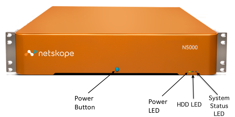
The N5000 is a 2U appliance best suited for management duties because of its expanded event retention capabilities but can be used in any capacity.
The front of the unit has a power button at the center, and a small bank of LEDs on the right side:
Important
Before turning off the appliance using the power button, log in to the appliance (using ssh or IPMI) and enter the command shutdown. Use the power button to turn off the appliance only after issuing this command.
The rear of the unit has several ports with specific purposes.

In a typical installation, the IPMI port is used for initial setup only, the inbound port is used for log parsing functionality, and the TAP port is used to receive traffic from a decrypting TAP.
Two AC power supplies are in the rear left of the chassis and provide redundancy. The following image shows the rear of the N5000 chassis.

Appliance LED Status
The appliance has three LEDs in the front – Power LED, HDD LED, and System Status LED.
The following tables provide details about of various states of the LEDs that indicate the status of the appliance.
Power LED
| Color | State | Criticality | Description |
|---|---|---|---|
| Green | Solid on | System OK | System booted and ready. |
| Off | N/A | Not ready | AC power is off. |
HDD LED
| Color | State | Criticality | Description |
|---|---|---|---|
| Amber | Solid on | HDD OK | HDD is active. |
| Amber | Blink | HDD OK | HDD is transferring data. |
| Off | N/A | Not ready | HDD is inactive. |
System Status LED (Alert LED)
| Color | State | Criticality | Description | Action |
|---|---|---|---|---|
| Red | Blink | Non-critical | Non-fatal alarm – system is likely to fail:
| Contact Netskope support. |
| Red | Solid on | Critical, non-recoverable | Fatal alarm – system has failed or shut down
Note This state also occurs when AC power is first applied to the system. This indicates the BMC Is booting. | Contact Netskope support. |
| Off | N/A | Not ready | AC power off, if no degraded, non-critical, critical, or non-recoverable conditions exist.
| No action |
System Specifications

Outbound Ports
Use these ports for management connectivity and log uploads.
For management connectivity:
| Domain | Description | Port |
|---|---|---|
config-<tenant-URL> | Use for configuration updates. The domain needs to be SSL allowlisted if you have SSL decryption enabled. | 443 |
download-<tenant-URL> | Use for software upgrades. | 443 |
messenger-<tenant-URL> | Use for reporting and status updates in the UI. The domain needs to be SSL allowlisted if you have SSL decryption enabled. | 443 |
callhome-<tenant-URL> | Use for receiving metrics from on-premises appliances and forwarding them to cloud tenants, as well as receiving event data from an on-premises dataplane appliances. Also for receiving custom user attributes from user endpoints. The domain needs to be SSL allowlisted if you have SSL decryption enabled. | 443 |
defupdate.<tenant-URL> | Use for downloading anti-malware definitions successfully. | 443 |
For log uploads:
| Domain | Description | Port |
|---|---|---|
upload-<tenant-URL> | Use for sending logs to the Netskope cloud with SFTP. This is the default port for log uploads. | 22 |
logupload-<tenant-URL> | Use for sending logs to the Netskope cloud with HTTPS. This port is enabled by default. | 443 |
<tenant-URL> | Use for fetching the REST API token with HTTPS. | 443 |
Inbound Ports
| Service | Description | Port |
|---|---|---|
| Syslog | Use for receiving syslog traffic. | 514 |
| AD Connector | Use for getting IP-to-user mapping with the Netskope AD connector. | 4400 |
| SFTP and SCP | Use for management connectivity and log uploads to the log parser appliance. | 22 |
| FTPS | Use for management connectivity and log uploads to the log parser appliance. | 21 (using explicit SSL) |
Note
Netskope does not support implicit SSL over port 990.
Prerequisites
Before you begin the installation, make sure you meet these hardware and software requirements:
- Hardware Requirements: To perform a successful install, you will need one temporary network cable for the IPMI port. You will also need two permanent network cables, one for the management interface port and one for the inbound interface port.
- Software Requirements: To access the remote console for the appliance over the IPMI interface, you will need to a working Java Runtime Environment. If you don’t have this, you can download it from http://www.java.com.